Exploring Multicast with PIM Sparse-Mode is a hands-on lab designed to help learners build an intuitive, visual understanding of how multicast forwarding works in a PIM Sparse-Mode network. Through a sequence of guided predictions, configurations, and packet captures, learners observe how receiver interest (via IGMP) triggers the creation of shared (*,G) trees toward the Rendezvous Point, and how the introduction of an active source later drives the formation of source-specific (S,G) trees. By inspecting PIM Join/Prune messages, multicast routing tables, and state changes over time, the lab’s objective is to move beyond rote configuration and help learners clearly understand why PIM Sparse-Mode behaves the way it does—how control-plane signaling precedes traffic, how the RP fits into the process, and how multicast state is created, used, and eventually removed.
This document walks back through the lab in the same order as the tasks, answering every prediction question along the way.
It also explains a few Cisco IOS behaviors that can otherwise be surprising the first time you notice them.
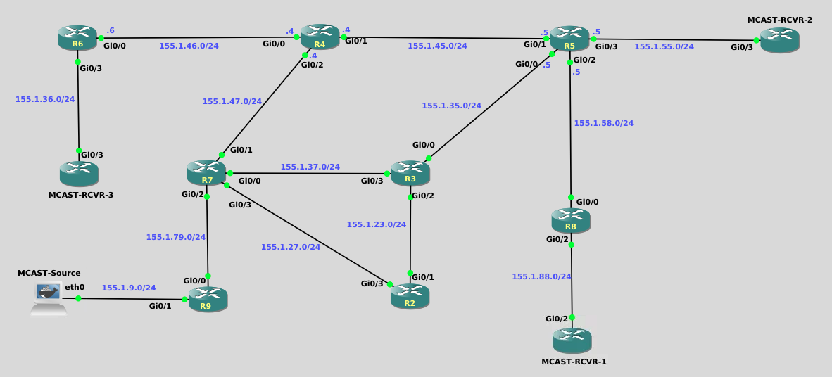
R2 through R9

ip multicast-routing
!
interface range gigabit0/0 - 3
 ip pim sparse-mode
 exit
!
ip pim rp-address 3.3.3.3
Multicast Receivers

MCAST-RCVR-1

interface gig0/2
 ip igmp join-group 225.9.9.9
 end

MCAST-RCVR-2 & MCAST-RCVR-3

interface gig0/3
 ip igmp join-group 225.9.9.9
 end
Before PIM can function, IP multicast routing must be enabled globally.
This is required on every router that will forward multicast traffic:
It is not required on the receiver routers (Mcast-Rcvr-1/2/3).
conf t
 ip multicast-routing
endBecause this lab uses a static Rendezvous Point, every router that participates in PIM Sparse-Mode must be told who the RP is.
conf t
 ip pim rp-address 3.3.3.3
end
R3 owns that address on Loopback0, but that alone does not advertise RP information.
Even though Mcast-Rcvr-1 / 2 / 3 are IOSv routers, in this lab they behave like multicast hosts:
interface <upstream-interface>
ip igmp join-group 225.9.9.9Question:
Do you expect any multicast routing entries to exist yet? Why?
Answer:
Not for your lab group, but you may already see one multicast entry.
When ip multicast-routing is enabled, Cisco IOS automatically creates multicast state for certain well-known control groups, even before any receivers join.
This is normal.
After multicast routing is enabled, PIM Sparse-Mode must be enabled per interface:
conf t
 interface gi0/0
  ip pim sparse-mode
 !
 interface gi0/1
  ip pim sparse-mode
end
This is required on: - Router-to-router links - Source-facing interfaces - Receiver-facing interfaces on upstream routers
It is not required on Mcast-Rcvr-1/2/3.
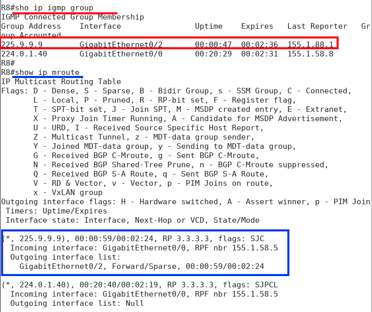
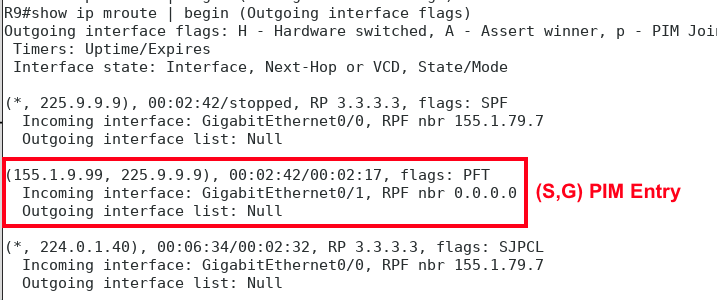
After enabling multicast routing, you likely observed something similar to:
(*, 224.0.1.40), RP 3.3.3.3This entry is not caused by a receiver joining your lab group.
224.0.1.40 is a well-known multicast control group used internally by PIM and other protocols.
IOS installs this (*,G) entry automatically so the router can:
 This entry exists even with zero receivers and no user multicast traffic.
What event causes the first (,G) entry for *your multicast group (225.9.9.9) to appear?
The first IGMP Membership Report for 225.9.9.9.
Control-plane groups (like 224.0.1.40) appear automatically,
but user multicast groups only appear when a receiver explicitly joins.
This distinction is important and intentional.
That single packet is enough to trigger multicast routing state for the group.
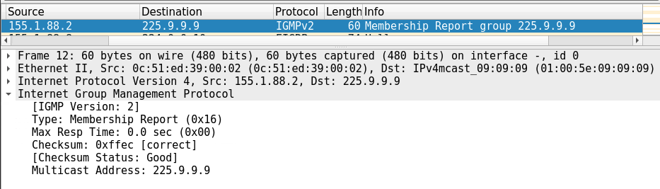
Sequence:
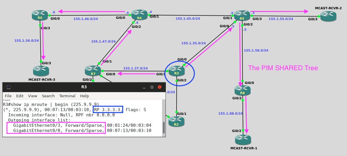
(*,225.9.9.9)R8 → R5 → R3 (RP)One receiver builds the entire shared tree.
Because the tree already exists.
PIM Joins extend trees — they do not count receivers.
When Mcast-Rcvr-3 joins:
Path:
R6 → R4 → R7 → R3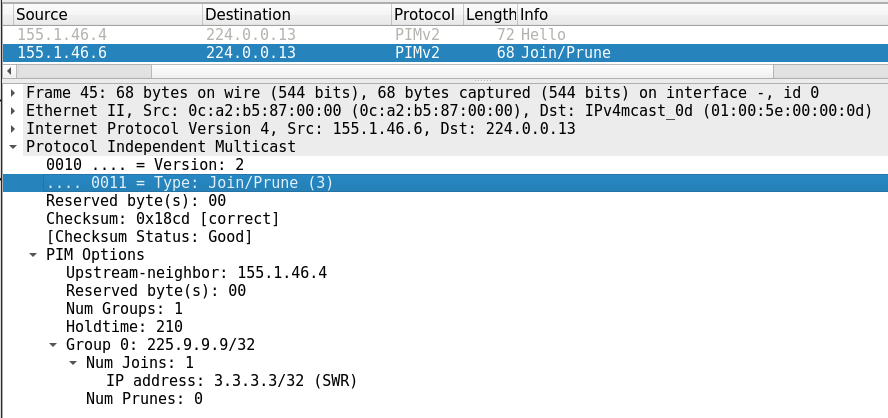
No source traffic exists yet.
Sparse-Mode always builds the shared tree first, rooted at the RP.
Why no new Join appears:
After adding the CLI commands to the MCAST-Source node and beginning the multicast stream, the sequence that you should have seen:
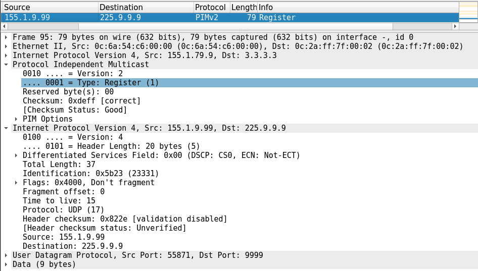
Closest to the source — starting at R9.
It introduces the source, then data traffic typically bypasses it.
When traffic stops:
Some multicast state exists because the control plane needs it.
Other multicast state exists because a receiver asked for it.
Knowing the difference prevents a lot of confusion — and now you’ve seen both.
End of Lab Solutions