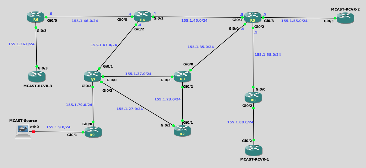
Welcome to the Dynamic Rendezvous Points with PIM BSR lab, where you will gain hands-on experience configuring and validating dynamic RP discovery using the PIM Bootstrap Router mechanism. In this lab, you will enable multicast routing and PIM Sparse Mode, establish receiver interest, configure Candidate RPs, and designate a Bootstrap Router to distribute RP information throughout the multicast domain. By observing control-plane behavior and verifying (*,G) state without relying on multicast data traffic, you will reinforce how PIM BSR enables scalable, standards-based RP selection in a routed network.
This solution walks through the required control-plane behavior and configurations needed to reach the correct end state. The focus is on BSR operation, RP selection, and verification, not multicast data forwarding.
With only unicast routing configured:
This lab is intentionally built so that receiver interest exists first, which makes RP selection obvious as soon as BSR and Candidate-RP configuration is completed.
Without IGMP joins, you can still verify BSR/RP state with show commands, but you may not immediately see meaningful (*,G) state for the test group.
On each node labeled MCAST-RCVR, apply on the receiver-facing interface:
ip igmp join-group 225.9.9.9You can confirm the join locally with:
show ip igmp groupsApply the following configuration on every router from R2 through R9:
conf t
ip multicast-routing
!
interface range gig0/0 - 3 , loopback0
 ip pim sparse-mode
end
After this, verify neighbors form where expected:
show ip pim neighbor
show ip pim interfaceR2 — Candidate RP
conf t
ip pim rp-candidate loopback0 priority 10
end
R3 — Candidate RP (selected RP)
conf t
ip pim rp-candidate loopback0 priority 0
end
Result: - R3 is selected as RP due to a lower RP priority. This will be verified momentarily.
R4 — PIM Bootstrap Router
conf t
ip pim bsr-candidate loopback0
end
Result: - R4 originates Bootstrap messages. - All routers learn the Candidate RP set and compute RP mappings.
Once Task 1 (PIM) is done, and after Tasks 2–3 are configured, verify both control-plane roles and that the group is using the intended RP.
show ip pim bsr
show ip pim rp
show ip pim rp mapping
Expected: - BSR = R4 - RP = R3 (for the appropriate group range / including 225.9.9.9)
```
R8#show ip pim bsr
PIMv2 Bootstrap information
  BSR address: 4.4.4.4 (?)
  Uptime:      00:00:12, BSR Priority: 0, Hash mask length: 0
  Expires:     00:01:57
R8#
```

```
R8#show ip pim rp mapping
PIM Group-to-RP Mappings

Group(s) 224.0.0.0/4
  RP 3.3.3.3 (?), v2
    Info source: 4.4.4.4 (?), via bootstrap, priority 0, holdtime 150
         Uptime: 00:26:35, expires: 00:01:38
  RP 2.2.2.2 (?), v2
    Info source: 4.4.4.4 (?), via bootstrap, priority 10, holdtime 150
         Uptime: 00:26:35, expires: 00:01:37
R8#

```(*,225.9.9.9) state existsBecause IGMP joins were configured at the start, you should now see (*,G) state for the test group:
show ip mroute 225.9.9.9Notice below that the mroute output confirms that R3 (3.3.3.3) has been elected as the PIM RP
R8#show ip mroute 225.9.9.9
IP Multicast Routing Table
Flags: D - Dense, S - Sparse, B - Bidir Group, s - SSM Group, C - Connected,
       L - Local, P - Pruned, R - RP-bit set, F - Register flag,
       T - SPT-bit set, J - Join SPT, M - MSDP created entry, E - Extranet,
       X - Proxy Join Timer Running, A - Candidate for MSDP Advertisement,
       U - URD, I - Received Source Specific Host Report,
       Z - Multicast Tunnel, z - MDT-data group sender,
       Y - Joined MDT-data group, y - Sending to MDT-data group,
       G - Received BGP C-Mroute, g - Sent BGP C-Mroute,
       N - Received BGP Shared-Tree Prune, n - BGP C-Mroute suppressed,
       Q - Received BGP S-A Route, q - Sent BGP S-A Route,
       V - RD & Vector, v - Vector, p - PIM Joins on route,
       x - VxLAN group
Outgoing interface flags: H - Hardware switched, A - Assert winner, p - PIM Join
 Timers: Uptime/Expires
 Interface state: Interface, Next-Hop or VCD, State/Mode

(*, 225.9.9.9), 00:30:24/00:02:39, RP 3.3.3.3, flags: SJC
  Incoming interface: GigabitEthernet0/0, RPF nbr 155.1.58.5
  Outgoing interface list:
    GigabitEthernet0/2, Forward/Sparse, 00:30:24/00:02:39

R8#On the receiver routers (and/or the MCAST-RCVR nodes):
show ip igmp groupsR8#show ip igmp group
IGMP Connected Group Membership
Group Address Interface Uptime Expires Last Reporter Group Accounted
225.9.9.9 GigabitEthernet0/2 00:31:33 00:02:27 155.1.88.1
224.0.1.40 GigabitEthernet0/0 00:31:35 00:02:29 155.1.58.8
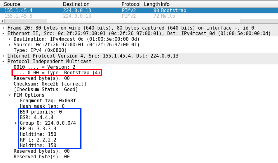
R8#Start a capture on a core link and look for PIM control-plane traffic. This validates that router state aligns with observed signaling.
(*,225.9.9.9) state exists across the domain